


These modules can handle and manipulate up to 50W of RF energy using feedback algorithms such as PID, Fuzzy logic, PWM or user developed
mathematical algorithms for a single electrode of any type of catheters. They also accept any type of temperature probes
for monitoring the tissue temperature during ablation procedures. Up to 8 modules can be cascaded via a backplane for catheters with
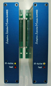
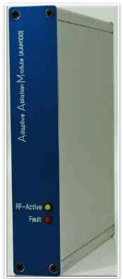
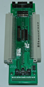
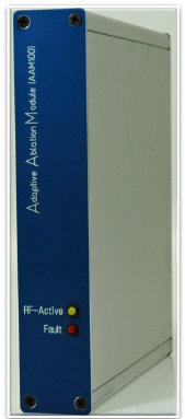
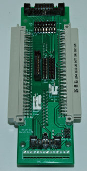
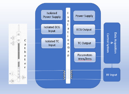
higher number of electrodes. They also can monitor physiological signals such as ECG during ablation procedures. Figure1, RF
Energy Management functional block diagram, figure 2, RF Energy management Module assembly, figure 3, single backplane board and figure
4 cascaded multiple modules backplanes.
· Maximum output power of 50W RMS
· Frequency range 380-480KHz (fixed 480KHz internal), programmable external at 1Hz resolution
· DAQ interface via front panel connector
· RF shutdown control switch
· Single pulse or PWM control signals input connector
· RF Active and RF Test indicators
· Programmable power control from fraction of a watt up to 50 watts RMS
· Programmable
Impedance setting from 25 up to 500 Ohms
· Programmable ablation time from 1 second
up to hours
· Mono or bipolar mode of operation
· Operational modes: Temperature, Power, Impedance, pulse or combination of all
· Parameter
monitoring including, Power, Impedance, Current, and Pulse Width
· Ease of graphical
programing in LabVIEW FPGA technology as well as MATLAB or other scientific programming languages