Double-click here to edit the text.
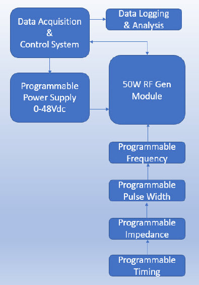
Small in size, only 7X5X2.5 inch that can be implemented into an existing design. It is designed to operate as standalone 480KHz RF generator with an external power supply (48 volts fixed or adjustable) or as part of an elaborate RF energy management system in a newly design system for precise control of RF energy delivery as well as monitoring of the RF signals parameters such as, power, impedance, voltage and current. Figure 1, 50 watts RF generator operational block diagram
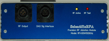
50W RF Generator Module
Radio Frequency Ablation Technology
Maximum output power of 50W RMS
Frequency range 380-480KHz (fixed 480KHz internal), programmable external at 1Hz resolution
DAQ interface via front panel connector
RF shutdown control switch
Single pulse or PWM control signals input connector
RF Active and RF Test indicators
Programmable power control from fraction of a watt up to 50 watts RMS
Programmable Impedance setting from 25 up to 500 Ohms or any values set by the operator
Programmable ablation time from 1 second up to any value set by the operator
Mono or bipolar mode of operation
Operational modes: Temperature, Power, Impedance, pulse or combination of all
Parameter monitoring including, Power, Impedance, Current, and Pulse Width
Ease of graphical programing in LabVIEW FPGA technology as well as MATLAB or other scientific programming languages
Programming Mode Features if operated via a data acquisitioning and controlling system.
Figure 1, 50W RF Generator Operational Block Diagram